RMC150E UI/O cards can be used as a servo simulator. Each card can simulate two axes. This document outlines the procedure for setting up a UI/O card as a servo simulator.
Axis setup
- In the Axis Definitions create a new Axis
- Select Cascading Outer Loop as the axis type
- Select Single Control Loop, Position feedback
- For the Position Input, select Custom
- Click Finish to create the axis. Note that this axis does not use any hardware inputs or outputs.
Simulator Setup
- Open the Axis Tools
- On the Parameters side, switch to the All tab
- Set the System Gain, Natural Frequency, Damping factor and physical limits.
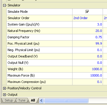
- Click the checkbox to enable simulate mode
Simulator Scaling
- In the Feedback section of the Axis Parameters, set the position scale.
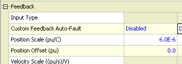
- The maximum number of counts will be the positive physical limit divided by the position scale.
- In this example, 100 / 6e-6 = 16,666,667 which is slightly less than 2^24, the maximum number of counts for 24 bit SSI.
Set up the SSI Output
- In the Modules section of the Project Tree, right click on the UI/O card and click properties
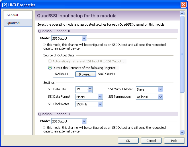
- Switch to the Quad/SSI tab
- Change the Mode to SSI Output
- Under Output the Contents of the following Register, click Browse
- Select Axes->Outer0->Status->Feedback-Primary->Counts
- Set the SSI Data bits, Binary/Gray code, SSI Clock rate, output mode and termination
Create Reference Inputs
- In the Axis Definitions, create a new axis
- Select Reference Axis
- For the Feedback type, select Velocity
- From the Velocity Input drop down, select a UI/O analog input
- Click Finish to create the axis
Create the User Program
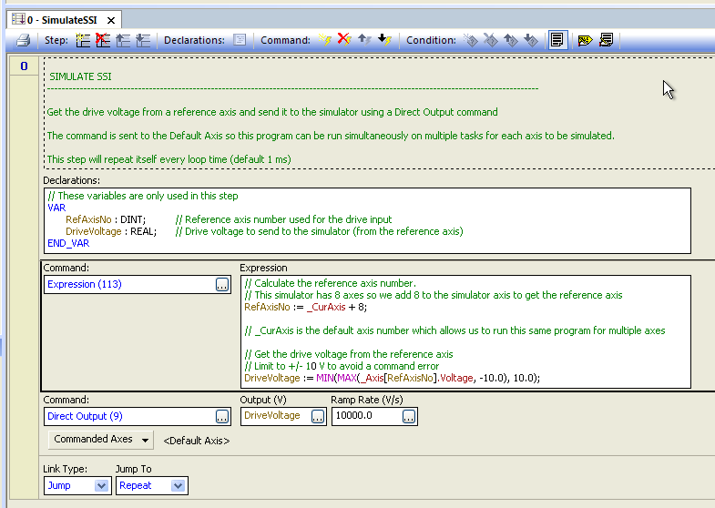
- A user program is necessary to get the voltage from the analog inputs to the simulator.
- Import the SimulateSSI program or create a new program with the following step:
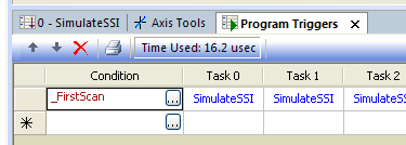
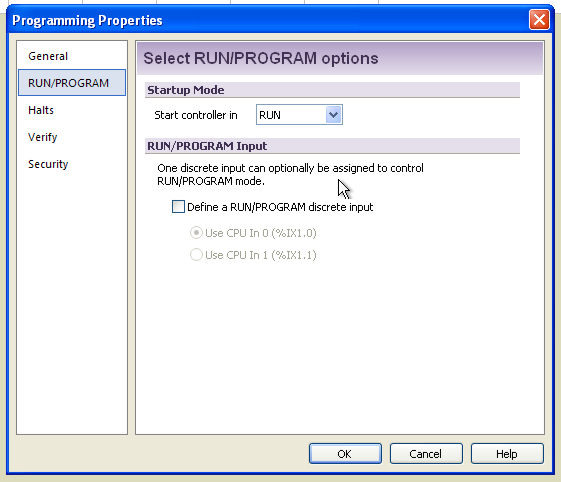
- Set the program to run automaticall on all axes by adding it to the program triggers on the _FirstScan condition.
- Set the controller to start in Run mode by right clicking on Programming and clicking Properties. On the Run/Program tab, select Start Controller in Run mode.
Download to the Controller
- From the Controller menu, select Download All To Controller
- From the Controller menu, select Update Flash
- Switch the controller into Run mode. The program will now start on all axes.
Monitoring Positions
- To check the Drive input, open the Axis Tools and select the All tab on the Status side
- Expand Feedback.
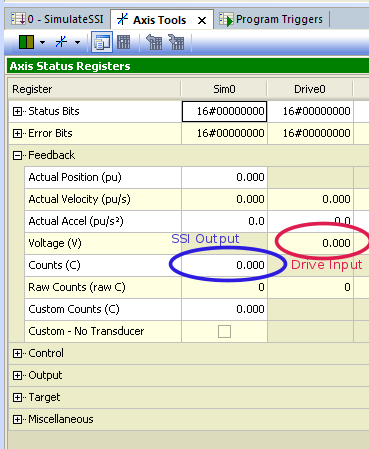
- The drive input will be the Voltage (V) register on the Reference Axis
- The SSI Output will be the Counts (C) register on the simulator Outer Loop Axis.
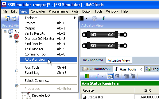
- You can show a graphical view of the simlated axes by selecting Actuator View from the View menu.
SimulateSSI.rmcprog (2.01 KB)
RMC150E UIO Simulator.pdf (244 KB)