Other than what’s in the RMC Help, is there a video tutorial here or a walk through for tuning a pressure axes? I see that there is an abundance of information and videos here for motion control support/help, but tutorials/videos for pressure control and tuning is lacking. I have to tune several axes for hydraulic pressure control where a servo valve is controlling flow to a hydraulic cylinder in order to control the pressure. Pressure range is going to be 0-2000 psi probably. This seems pretty non-trivial but I need to verify - should the system be dead heading when I’m doing the tuning?
Unfortunately, the pressure tuning is indeed a bit lacking. We will work on improving that.
When tuning pressure, the axis should be exerting pressure on a load, or at least be extremely close to it, otherwise when you enter pressure control, the system will try to apply a pressure, and if there is no resistance, the axis will go shooting ahead.
The general procedure I use is as follows, in the Tuning Tools:
Move the axis to where it is exerting pressure , or is extremely close to it.
Set the pressure proportional gain to a small value. For a typical hydraulic cylinder using psi units, a value of 0.001 is probably safe.
Send the Hold Prs/Frc command. If the axis jumps or bangs, the P gain was probably too large. Keep in mind that if the axis faults, you will have to specifically enter pressure control again.
Increase the proportional gain so that the Actual Pressure gets closer to the Target Pressure .
Ramp the pressure and look at the plot.
Once the plot shows the axis is following somewhat, you can use the tuning wizard to finish the tuning. In the pressure tuning wizard, choose the last plot you made, and the wizard will calculate the model and provide the slider bar from which you can select gains.
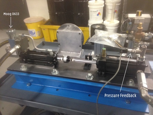
Okay. I will plug off all ports on the system so that we are guaranteed to be exerting pressure. I read through the section in the RMC Tools Help for tuning a pressure axes and it doesn’t seem too difficult and our system is not complicated. It’s basically a small hydraulic cylinder actuating another hydraulic cylinder (secondary). The secondary cylinder is where we need to be able to control the pressure so that is where our pressure feedback transducer is located. I have limited experience tuning PID loops. I’ve tuned PID loops for heat control but all I needed was the P and I terms to get it controlling correctly. I trust that tuning this pressure system will need more than that. Our end operation is expected to ramp (S-curve) from 0-1200 psi and hold there. Ramp target time is 50mS or less.
You can probably just run the cylinder all the way out to exert pressure on the end of the stroke and tune it just like that. We do that sometimes here.
The transducer is not in the cylinder with the valve so he will need to get the oil in the bore of the secondary cylinder under pressure and then close off that circuit.
Depending on where the secondary cylinder is in its stroke and the volume and compliance of the connected vessel it will take more or less stroke to compress the oil to get your desired pressure. Planning on doing something similar myself soon.
I worked on tuning the axes today. Most of my tuning was all manually done but I did try using the wizard after I had a fairly “okay” plot. Using the slider after that didn’t help, but then again, I may not have had a good enough plot to begin with? I manually tuned after that and finally got a satisfactory plot. I did not use the wizard after, but I do plan on uploading that plot and using the wizard and see what I can get from that tomorrow or Monday. Hopefully, it allows me to get a tighter tune.
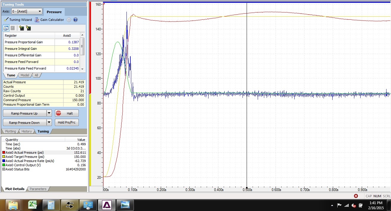
As stated, I did find that I got a more consistent plot trace when the cylinder is exerting at least a little bit of pressure to begin with. My target was to ramp to 150 psi in 100mS. (Is this doable in 50mS??). I will upload a snapshot of my trace on my next post when I get a chance. I had to use a lot of Pressure Feed Forward Rate. The trace is far from perfect but it was as close as I could get it by manually tuning. It spikes to my target pressure in roughly 100mS target time, then quickly drops about 20 psi, then takes about 10 seconds to come back up and level off at 150 PSI. That last part of the trace is the part of the trace I need to fix as I feel that’s too slow. I was struggling trying to fix that and really didn’t know what term to adjust as I felt like I was chasing my tail at that point. Per your advice, I set the P term to .001 to begin with but I was not seeing any reaction or if I did, it was VERY slow. The documentation states “until the pressure begins to move towards the target”. Does it matter how fast or how slow it moves to the target with the initial P term setting?? Because I found mine to be moving, but at a snails pace. If you were just looking at the trace itself and not the pressure value, it would be hard to tell if it was moving. So, I bumped up the P term a little until I could see it moving and leveling off at around 40-50 psi? That took several seconds. Was that too much P-term? Then, as per the help files, I adjusted the I-term roughly twice that of the P-term. That caused heavy overshoot of the target pressure right away. In fact, I believe I had the P term at .001 and the I-term at .002 and I was getting heavy overshoot. I don’t recall everything I did after that but all of my terms (P, I, D, and PFFR) were all very low values (.001 or less). I will upload a snapshot of my trace and the tuning values on my next post.
Also, if I’m holding pressure at 150 psi against a directional valve in the system, and then open that directional valve to allow flow briefly, what affect will that have on my plot?? I need the axes to hold pressure as tightly to 150 psi as possible, even when I open the directional valve. In theory, my thought is that if I issue a “Hold Pressure” command after I’ve ramped to my target of 150 psi, then when I open the directional valve, the axes should continue to hold that pressure with little or no pressure drop. Is this correct?
I would first make sure you have all of the air out of the secondary cylinder. From the picture it is hard to see how you are filling this side with oil. My idea is to have a low pressure supply into the piston chamber through a check valve. Then slowly move the cylinder back and forth to fill with oil (there are a few more components needed but hopefully this gets the idea across).
Also, the seals in the secondary cylinder are going to play havoc on your tuning if they have any sticktion. You will build up and then always overshoot when the seals transition from static to kinetic friction. So there is a conflict between having seals with little friction that will likely leak a little
I suppose, theoretically, when you open a valve on the system, if it all was designed and tuned you could sustain a pressure but only until the end of the cylinder stroke. Maybe it’s a small valve and this doesn’t matter.
A circuit schematic would help with understanding what you are trying to do.
Attached is my plot. I’m hitting my target of 150 psi but it quickly drops (too far) and then takes several seconds to come back to target and settle. Also attached is a schematic of my system. Circuit Drawing 10.28.14 from JE myles.pdf (72 KB) MyPlot.rmcplots (121 KB)
I used the plot that I posted before in the tuning wizard and then used the slider to adjust and play with tuning parameters. This worked a lot better. I did have to manually adjust the pressure rate feed forward though as the slider was not making adjustments to that parameter when I moved the slider. Here is what I have for a plot now. I think it looks pretty good but a more experienced person/s may think differently. Thoughts? Can this tune be dialed in any better?
Whether or not the control is good enough depends on the specs for your machine operation. Given that there is not much oscillation or noise in the Control Output, it looks like you can increase the gains a bit more to improve the control.
Opening up the proportional valve to allow flow briefly ( I assume you mean in the load circuit) will certainly affect the control. The axis will certainly continue to try maintaining pressure, and when things change such as this change in the system, the P, I , and D gains are instrumental in trying to maintain pressure. The Rate Feed Forward only applies when the Target Pressure is ramping. You do not need to send the Hold Current Pressure command after ramping. After a ramp, the axis will still try to maintain the pressure that was ramped to.
Notice that the feed forwards are not expected to change when moving the slider bar in the Gain Calculator. The Gain Calculator is fairly good at calculating the feed forwards, assuming the plot was decent.
Thank you for clarifying. It appears that this amount of control will be sufficient for our needs.
Unless the gain calculator resets the control output filtering to 0 when uploading a new plot for calculating gains, then there is a filter applied to the output of that plot, hence the low oscillation. I don’t recall what I had it set at when I first started manual tuning last Friday, but I did add filtering to smooth out the high oscillations on the output that I was seeing . I didn’t check or verify filtering today since I was able to get a good trace with the gain calculator and slider bars, but I can play around with filtering again tomorrow and see where its set at.
After each manual cycle of the system, I would hit the Halt/Stop button and of course the system would slowly release pressure. During the ramp down, I would occasionally hit the “Hold Pressure” button to see how well it could hold. It was pretty good - fast response time and holding steady. So…hopefully there shouldn’t have to be any changes on the fly to the gains when we try opening up the directional valve while pressure is applied.
I didn’t realize you had output filter applied. I checked the plot file you posted previously and it was set to 0.3, which is way too low. The Output Filter parameter is the cut-off frequency for a low-pass filter, so you should start with a high value such as 100, then decrease it to apply more filtering. I think you will get much better results if the Output Filter is a bit higher, like 10 or 20. You will likely need to decrease the gains then, or there may be too much oscillation.