For someone starting to learn the care and feeding of a Delta Monton controller, It’s a rare treat to see many fine publications , manuals and video tutorials that are so well written. I’ve made progress communicating with my RMC75E, following many of the examples in the tutorial. All is going well.
Because I am not controlling anything hydraulic, I’m a little outside the typical with this manual, and must request a little help with the wiring.
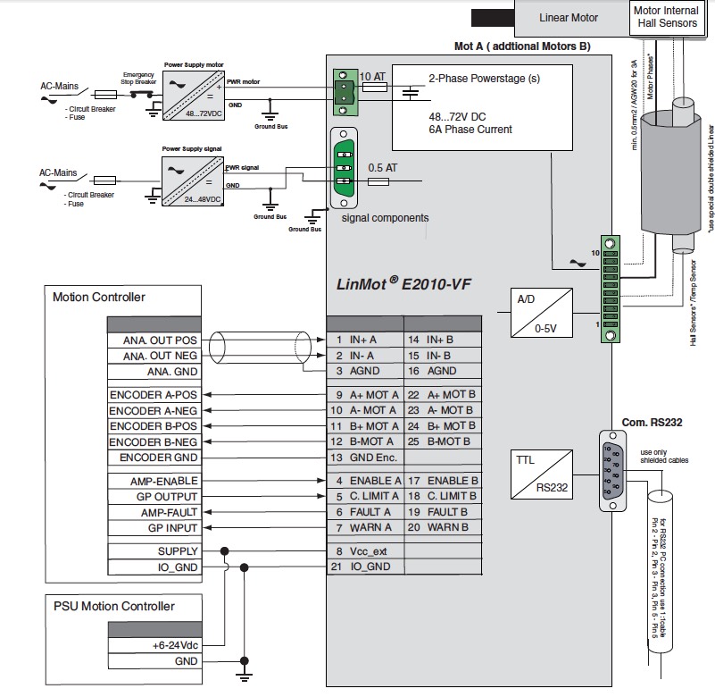
At first look… this seems like a slam-dunk to me. The ”actuator” has internal quadrature feedback (+5V) from hall effect sensors. And, the servo controller is intended to have a motion controller for it’s brains. Here’s how LinMot thinks it ought to be connected:
The RMC75E-QA1-AP2-D8-D8 I’m using will be upgraded with a QA2 if all this works out. (using this older LinMot VF Driver for practice.)
I’m not asking how to make this work… That’s my job to figure out… but, I don’t want to do anything to harm the RMC … Please skim this info, and see if there are any red flags, or something that jumps out at you, … that I may be misunderstanding.
The Quad cable, from the RMC (below) isn’t quite using the same terms used in the LinMot diagram (above)
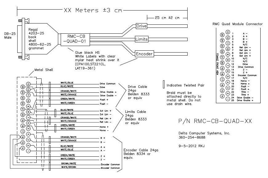
Only talking about one axis here (Drive A), and the Delta Quad Cable diagram…
Here’s how I see it:
DRIVE CABLE
-
“Drive Common” (pin 13) most likely connects to Drive (Pin 2) … on LinMot
-
“Drive" (pin 12) should be control voltage out to Drive (Pin 1)
-
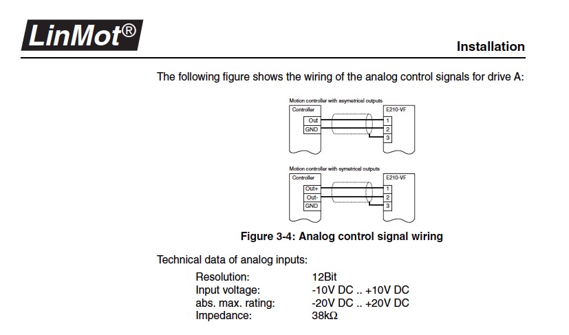
LinMot’s analog ground (shield) might or might not be connected to Delta’s shield? … See below
What’s illustrated here is not real clear to me … the shield is going to be connected to the RMC, by the Dsub25 plug. I understand the analog control signal from the RMC is configurable. I would like it to vary from zero to +10VDC. like the asymmetrical output illustrated. So, I would not connect anything to LinMot’s pin 3. -
Drive Enable and Fault are Digital I/O’s (24 VDC) … Drive Enable “+" (pin 25) connects to Drive (pin 4) … on LinMot
…not so sure what to do with Pin 24 … Drive Enable “-“ …probably connect to common LinMot (Pin 21) -
Fault “+” would connect to Drive (pin 6) … on LinMot … again… not sure what to do with Delta pin 20 … Fault “-“ again… LinMot (Pin 21)
LIMIT CABLE (more Digital I/O’s)
6) Positive and Negative Limits will not connect to the LinMot Drive (but, would use the same power supply as the RMC)
7) Home will be a switch … again using the same power supply as the RMC.
I’m thinking these Delta digital I/O’s require a common power supply … assuming it’s same power supply that provides the RMC with 24VDC? … Those I/O’s with twisted pairs in the Limits and Drive cables have + and - wires… they are expecting an INPUT voltage, to match those polarities, and will OUTPUT a voltage at those polarities.
The LinMot requires an “externa” I/O Power supply (6 to 24 VDC) … and it expects that power supply is common with the I/O’s from Delta. (as shown in the diagram above.) There is no I/O power to the QA1 other than the 24 VDC main 3 pin connector on the RMC75 CPU
- So, at this point, I would also connect the Delta RMC 24 VDC Power supply to LinMot Pins 8+ and 21- … as shown above. (whew!)
ENCODER CABLE
That’s definitely slam-dunk… 
By the way… I’m not sure what their GP input and GP output is … it’s not mentioned in their manual. I’ll research the meaning of WARN and C. LIMIT an’ see what I can find.
Thanks so much for checking this over.
Regards, Michael Lambert