The simple equation. This is good to get an approximation for the natural frequency in radians per second, { \omega }_{ n }=\sqrt { \frac { 4\cdot \beta \cdot { Area }_{ avg }^{ 2 } }{ Mass\cdot TotalVolume } }
The basic formula for the natural frequency in Hz. { Hz }_{ n }=\frac{\sqrt { \frac { 4\cdot \beta \cdot { Area }_{ avg }^{ 2 } }{ Mass\cdot TotalVolume } }}{2\cdot\pi}
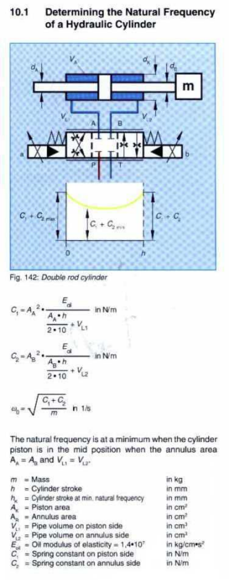
More precise equations. { Hz}=\frac{\sqrt { \frac { \beta }{ Mass } \cdot \left( \frac { { Area }_{ a }^{ 2 } }{ { Area }_{ a }\cdot \frac { CylLen }{ 2 } +{ DeadVol }_{ a } } +\frac { { Area }_{ b }^{ 2 } }{ { Area }_{ b }\cdot \frac { CylLen }{ 2 } +{ DeadVol }_{ b } } \right) }}{2\pi} Where: \beta \; is\; the\; bulk\; modulus\; of\; oil Mass\; is\; the\; mass\; of\; the\; piston,\; rod\; and\; load CylLen\; is\; the\; cylinder\; length DeadVol\; is\; the\; volume\; between\; the\; valve\; and\; the\; piston\; when\; fully\; extended\; or\; retracted
So why bother?
The natural frequency determines how fast the load can be accelerated or decelerated under control.
So if I have a 4" dia. cylinder with 2.5" rod, 12" long. And that cylinder is moving a 1000LB mass and is in the center of the stroke I am calculating the frequency like this (neglecting dead volumes).
I’ll go with 180,000psi for the Bulk modulus.
For a well-designed system with a high-performance, linear, zero-lapped valve, good position feedback, and reasonable friction behavior, the natural frequency should be about 3-4 times the frequency of acceleration. This assumes a PID with velocity and acceleration feed forwards. If we add the second derivative gain and jerk feed forward, the ratio can be lower.
The ratios are all approximate, as it depends on acceptable settling time and position error tolerance for any given application.
As Peter says, natural frequency is useful to consider, but doesn’t make anything move. More is required to determine correct cylinder area. Peter has enhanced Jack Johnson’s VCCM equation to determine the required cylinder area to achieve a certain acceleration. I am not sure where this info is readily accessible. Maybe Peter will chime in.
The frequency of acceleration is easy to determine if the motion is a sine or cosine wave. It is simply the frequency of the wave. Testing applications that use sine or cosine waves need to have actuators and loads that have a much higher natural frequency than the frequency of the sine wave if the controller is going to able to make the actuator follow the target sine wave. A long time ago, when using a RMC100, I determined the natural frequency had to be at least 3 times the frequency of motion. Actually 4 times was much better. I determined this by simulation. Back around the year 2000, the RMC100 and HYD02 only had a PID and velocity and acceleration feed forwards.
So why the RMC100? The RMC100 uses cosine ramps for the velocity.
Ramp up v(t)=\frac{1}{2}\cdot\lgroup1-cos\lgroup\pi\cdot\lgroup\frac{t-t_{0}}{t_{1}-t_{0}}\rgroup\rgroup\rgroup
Ramp down v(t)=\frac{1}{2}\cdot\lgroup1+cos\lgroup\pi\cdot\lgroup\frac{t-t_{2}}{t_{3}-t_{2}}\rgroup\rgroup\rgroup
So if a RMC100 ramps from 0 to 10 ips, it will move 0.5 inches. If the RMC100 then ramps down in 0.1 seconds it will move an additional 0.5 inches. So the RMC ramps up to 10 ips in 0.5 inches/0.1 seconds and down in 0.5 inchs/0.1 seconds. Notice the total motion is a cosine wave that takes 0.2 seconds or 5 Hz. This mean the natural frequency needs to be 3-4 times 5 Hz but it is best to if the natural frequency is 4 times when using a PID.
Below is a link to a move using a cosine ramp. It ramps up from 0 to 100mm/s at 1000 mm/s^2. This takes 0.1 seconds. Then it ramps down to 0 mm/s at 1000mn/s^2 and this takes 0.1 seconds more. All together the cosine makes a complete cycle in 0.2 seconds so the frequency of acceleration is 5 Hz. The hydraulic actuator should have a natural frequency of about 20 Hz if the actuator is going to make this move accurately when using a PID. However, if you look at the plot you can see the natural frequency of the actuator and load is only 10 Hz. The reason why it the actuator tracks the target position so well is that is it using our special algorithm.
This is much better
Cosine move with our special algorithm when the natural frequency is 10 Hz
Notice the second derivative gain and jerk feed forward are used. Cosine Move Using Advanced Algorithm
So why bother?
The natural frequency is roughly proportional to the diameter of the cylinder. If one can get by with a smaller diameter cylinder so that the natural frequency is only two times the frequency of acceleration, then one can save a lot of money because the required flow will be much less. Smaller cylinders and valves may be good enough. Of course this is still subject to the need to accelerate and decelerate the load.
So the power point is where the answer to my question lies.
I believe it is wrong and confusing to use the term “frequency of acceleration” when not speaking of sinusoidal motion. It leads to the question I asked earlier, how can you go from an an acceleration in distance\over{time^2} to frequency in Hz or rad\over{s}. The answer is you can’t.
What we really should be talking about is the frequency of the acceleration phase of a move. There is the implication that the accel/decel part of the motion is repeated continuously. This is where the frequency is deduced from. Theoretically you could do a FFT (Fast Fourier Transform) on the acceleration but that would be overkill and the dominant frequency would still be what you calculate from
{1\over{accel time + decel time}}
I’ll work up some real world number examples later
You are right about \frac{1}{acceltime+deceltime}
as long as the two times are equal.
I have done FFTs on motion profiles. The result is that there is one very low frequency that approximates the whole move, then comes the frequency components of the acceleration and deceleration ramps. Stopping the acceleration and deceleration ramps introduces higher frequencies which are of much lower amplitude so in a strict sense you are right but your simple formula above is good enough for practical purposes.
So why bother?
People are clueless. I have had customers tell me they had to re-tune the system when making short moves. The truth is that they didn’t change the acceleration and deceleration ramps so they trajectory never reached the desired speed so the ramp times were too short. This increases the frequency of acceleration so much that the hydraulics couldn’t follow the motion profile.
There is a cure, fix or work around. Even the RMC100 had time ramps so that even when making a very short move, one could set the ramp times to 100 ms so that short moves took a minimum of 200 ms. This kept the frequency of acceleration limited to 5 Hz even on short moves.
In other words, if the natural frequency is 20HZ, the minimum move time should be 200ms unless…
You are using a RMC75, RMC150 and RMC200.
@ndzied1, I agree that it’s not entirely accurate to use the term ‘frequency of acceleration’ when the acceleration profile is not sinusoidal. However, determining the required natural frequency based on the acceleration is approximate to begin with, and we have found that for this inexact purpose, an s-curve velocity profile is close enough to a sinusoid.
I really like the intuitive nature of comparing frequency of acceleration and natural frequency. I have seen textbooks that determine a required natural frequency with some cryptic calculation of the move parameters, and it is given only as a formula, with no intuitive explanation to it. To an engineer who is familiar with thinking about frequency components, comparing frequencies makes total sense.
For the s-curves used by the RMC, converting acceleration as a rate (e.g. in/s2) to the approximate frequency is very simple if the velocity is included. This is because the RMC actually calculates the acceleration time with the simple trapezoidal velocity formula (V1-V0)/A (after that, the RMC fits a 5-th order curve to the velocity to get a nice s-curve that is fairly close to a sinusoid). The frequency is simply the inverse of the calculated time, 1/(V1-V0)/A.
And yes, it would be much simpler if the RMC75/150/200 had an option to specify acceleration as a time, although that has it’s own issues. Maybe someone starts by specifying 0.2 seconds acceleration for a slow move, and forgets to change it on a fast move, and wonders why it can’t accelerate as commanded.
It is little bit confusing to understand the dead volume term in natural frequency equation.
Because dead volume is mentioned as, volume between valve and piston when fully extended or retracted.
So confusion here is, when to consider fully extended & fully retracted condition?
If we have equal area actuator then, how it will affect the dead volume consideration?
Please help.
Confusion is because of one statement, I have came across is " Natural frequency is minimum when cylinder piston is in mid position."
So why to consider dead volume at fully extended & fully retracted conditions?
I think is it helpful to think of a mechanical analogy. A hydraulic cylinder acts like a mass suspended between two springs. When the cylinder is in the middle of stroke, both springs are partially extended. The natural frequency is lowest in this state: it is hardest to control accurately, because exerting a force on either spring will store some energy in the spring before the mass starts to move.
Most of the time, you would probably want to consider the lowest-frequency case - that is, when the mass is in the middle of stroke. HOWEVER, it depends completely on the system design. If the control is not critical at the middle of stroke, and most of the accurate positioning or force control will happen closer to the ends of travel, then you can safely ignore the middle of stroke. You may also find from analysis that the difference in natural frequency between the middle and out towards the ends is so small that it does not make a difference for system control.
In short, the importance of this calculation depends quite a bit on what the cylinder is expected to do, how tightly the cylinder is to be controlled, and where in the travel range the cylinder is expected to work most often.