Currently we are testing one servo-actuator with 0.5mm displacement @ 0.5Hz frequency.
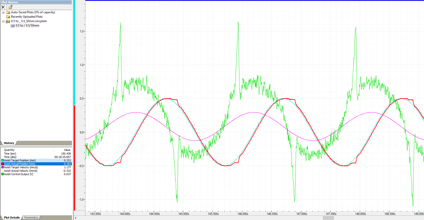
What we found is that actual position profile is not following targeted one at position where cylinder changes its direction…
Also, we came across one statement in research paper that we have referred “Very small displacements and corresponding low velocities can be unobtainable because of friction and its non-linear nature at low velocity”
Can anyone explain this statement??
Is there any control strategy available in RMCtools to overcome this issue?
I have attached exact plot that we have traced during testing.
Do you know what type of seals are in the cylinder?
We have actually taken the seal out of the piston in the past to reduce friction. This is not ideal but can help in a system already purchased. Cast iron ring piston seals are usually the lowest friction piston seals readily available.
The rod seal may still be enough to cause problems.
Companies like Moog and MTS sell special testing cylinders with very low friction seals to avoid things like this.
Cylinder has slipper seals (Bronze filled Teflon seal with O-ring energizer).
Ok, Now I got the point, why manufacturer like MTS or Moog prefer hydrostatic bearings for guiding cylinder rod precision application servo actuators.
The statement “Very small displacements and corresponding low velocities can be unobtainable because of friction and its non-linear nature at low velocity” can be explained by considering both static friction and dynamic friction. In fluid-lubricated contacts, friction is usually largest when there is no movement between two surfaces. As movement increases, that friction drops quickly. As movement further increases, the viscous friction increases. The chart of friction vs speed initially goes down, then up. See Stribeck curve in Wikipedia for a nice chart.
What this means is that at very low speeds, the system tends to stop. This is exactly what is shown in the plots you posted - as the velocity goes toward zero, the sudden increase in friction causes the velocity to go to zero. What can make this worse is that it takes some force to get it to go again, and when it finally does go, the friction suddenly drops, and the force that it took to get it going may now be too large, causing the speed to increase too quickly. Fortunately, the plots you posted don’t show this effect significantly, and your Actual Position doesn’t overshoot the Target Position (although the Actual Velocity certainly exceeds the Target Velocity, but it must in order for the position to catch up). This effect is more pronounced in systems that store energy. For example, if there is a lot of hose between the valve and cylinder, the buildup of force means the hose stores some energy, and a sudden reduction of friction results in all that force being released, tending to cause overshoot.
-Jacob
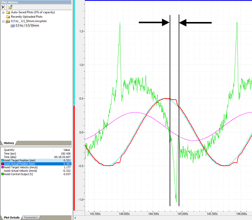
I thought it was interesting looking at the area between the arrows. We don’t know the output scaling in the plot. But if it is +/-10V then the valve is trying very hard to get the cylinder to move after a reversal. Position is standing almost still as the valve output gets bigger and bigger. Then, presumably when the friction “lets go” the position goes back to following the target.
I wonder if increasing the system pressure (if not maximum already) would help?
How increase in pressure will result in better plot? curious to know…
Currently, we are testing actuator without load i.e. no load connected to rod end.
Why I am asking this because servo valve try to move the load with force imbalance (pressure imbalance) across cylinder piston & how fast valve create force imbalance is function of flow that we get from the source.
Correct me if I have wrong understanding
Increasing the supply pressure will result in the pressure on the piston increasing more quickly when the valve opens in response to the increasing friction. It is similar to what you said, that it is a function of flow from the source. In this case, the source is the supply pressure, and we always assume the supply pressure itself has more than enough flow (this usually requires an accumulator). When the valve opens, it takes some time for the oil to flow through the valve, and there is a corresponding pressure drop. If the supply pressure is increased, the pressure drop across the valve is larger, resulting in faster flow into the cylinder, which increases the pressure more quickly, so the system can respond faster.
For these situations, it is important that the system is stiff. As I explained above, if there is significant energy storage between the valve and cylinder, it causes problems. Mounting the valve directly on, or very close to, the cylinder, makes the system more stiff (increases the natural frequency). Using hard pipe instead of hose is important. Also, a large cylinder diameter results in a stiffer system.
I am not sure, but there may also be other effects as a result of increasing the supply pressure.