I am using a pressure axis with a reference axis in RMC Tools. Both axis’ have actual pressure and pressure rate filter adjusting in RMC Tools. I’m hazy as to what the filters are for for the Pressure Axis and what/why I would need to adjust those. All I want to do is smooth out the signal from my reference axis (pressure transducer) as it is a bit noisy. I do that in the fields for the Reference Axis, correct? Do I also need/should adjust those for the Pressure Axis (Servo valve) as well??
Also,
I will be ramping pressure from 0-336 psi and anywhere in between at rates as low as 50 mS. Noise on my reference axis signal is about 1.5 lbs pp scaled. Transducer that I’m using is 0-700 lbs with a 0-10 VDC output. Any tips on where a good starting point is for my filtering for the reference axis (and pressure axis if needed?) ? Acceptable accuracy is obviously as best as I can get by with but I can settle for ± 0.25 lbs.
Thank you
Edit:
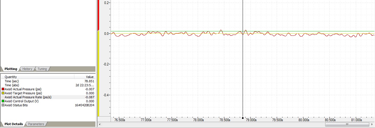
Attached is a snapshot of a 10Hz filter applied to my Reference Axis transducer. The noise on the signal may smooth out naturally once I have a load on it as this was set up with the transducer measuring in the dirt. I kept the pressure rate filter at 500 Hz since I don’t know where I should set that at or if I even need to mess with it at all? Sampling rate was 1000 Hz. Is this a good starting point? Do you feel that this may be too much filtering to allow good control for my needs?
You have the right idea. The filters are used to reduce noise but this comes at a cost which is phase lag. It is OK to filter the reference as much as you want. The lower the frequency the more the filtering because it is attenuating frequency above the frequency you specify. The usual problem us 50 or 60 cycle hum. A 10 Hz filter should be good for that but it is best if you find out what is causing the noise.
You should not filter the feedback for the closed loop control due to the phase delay it causes. Phase delay will allow the system to oscillated more easily. In this case it is best to find out what is causing the noise and use as little filtering as possible to keep the system response high.
500 Hz for the pressure rate filter is OK but don’t go much lower. At 500 Hz you are filtering out the sampling noise but nothing else. Sampling noise has not been a issue since each millisecond we read the pressure senso 8 times and do filtering on that in the FPGA. It is the machinery noise and 50 or 60 cycle hum that are bad. From looking at your plot it is hard to tell where the noise would be coming from because the 10Hz filter has done its job.
Look in the on-line-help. There are wiring diagrams there.
Peter,
Thank you for the reply. You say that it is okay to filter the reference as much as I want but I should not filter the feedback for the closed loop control. The reference is my feedback for the closed loop control. So therefore, I shouldn’t apply filtering to the reference, correct?
The wiring for the control axis and the reference axis is correct. I set this system up a while back on a temporary test stand when we were doing some valve testing and it worked fine. I was able to set it up, tune the axis, do the testing. Worked great. Feedback transducer was of a different make and size but wiring was still the same as to what I have now. At that time, I did not apply any filtering to the reference axis (my feedback for closed loop control). The only filtering that was applied was on the Pressure Output Filter for tuning (in the tuning Pane/Wizard). That amount varied depending on what pressure I was ramping to and at what rate. I did have to adjust it at times, but was still able to tune and get the solid control I needed. I am setting up a machine now that will utilize a very similar setup to what I was doing on the temporary test stand before. So maybe I don’t require any filtering on the reference Axis?. I suppose all I can do is test the system with both filtering applied and none applied and see how it responds.
I’m not sure what’s going on with the noisy signal on the reference axis feedback. Wiring is pretty straight forward - 24VDC Excitation, single ended output to the RMC controller. Again, I have no load on the signal and its measuring in the dirt (0 lbs). Maybe this “noisy” signal (1-2 lbs pp when measuring in the dirt) with a 0-700 psi transducer is “normal”? I’ll try to do some testing of it today and see what I get out of it both with filtering applied to the Reference and none applied.
I will post another snapshot of the plot showing the Reference Axis with no filtering applied so you can see a comparison between that and the 10Hz filter.
Thank you,
Don
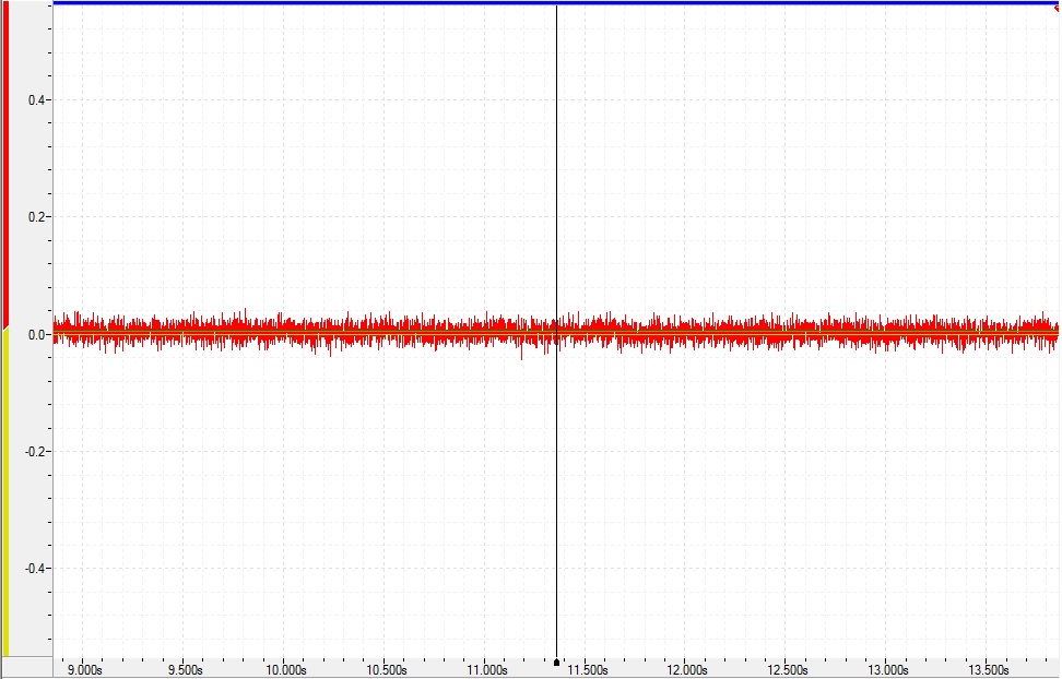
Here is the plot with no filtering applied (Reference Axis, pressure transducer used for feedback of closed loop control). It is scaled for full scale (0-700 lbs).
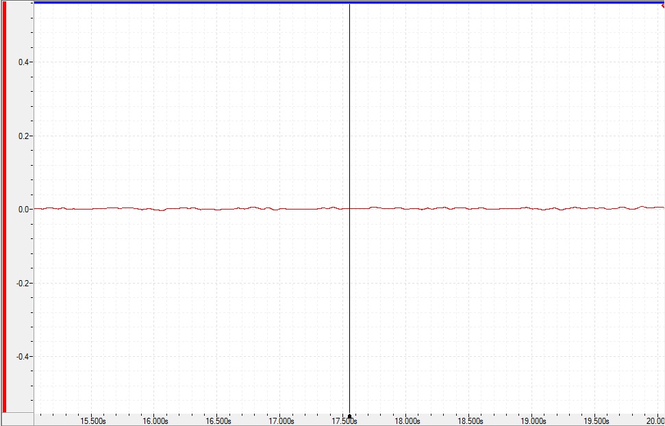
Here is the same Reference Axis plot with a 10 Hz filter applied.
The noise on the signal with no filtering does not look to me like a noise problem from wiring. I think this is fine (?), but a more expert opinion might be in order.
Thank you,
Don
I use the term reference for things like joy sticks or master axes to gear to. What you call reference I call feedback. In process type industries it is called the process variable or PV.
Don’t filter the feedback much if at all.
What you should do now is to sample this data as fast as you can. Go into the plot editor and set the sample time to as short as possible. 1ms should be default but 0.5 millisecond should be achievable. Now is should be easy to see if there are spikes or ripples that occur every 16 ms ( 60Hz mum ) or 20 mm ( 50 hz hum ). It is also possible to see if the spikes or ripples occur at the same rate as a local motor turning or some other source of noise.
Hopefully your feedback device is using a differential pair of wires.
Note, to Jacob. If we could do FFTs on plot data then would could identify sources/frequency of noise easier. We could also let customers know the frequency components of their motion profiles.
I keep calling it “Reference” because that’s what it’s labeled in RMC Tools. But yes, its the feedback or PV. Okay, I’m going to leave the feedback unfiltered. I’ll try the tip you suggested to see if noise is coming from an AC source somewhere on the machine. I’ll keep that one in my back pocket for future use as well