Screenshot_20260416_094455|690x229
To achieve greater flow, I want to connect four G761 servo valves to one channel of the VC2124. I plan to use the parallel connection method for the G761 valves. How should I connect them?
The basics of connecting one VC2124 channel to multiple valves is fairly straight-forward and is explained further below. Here are some important things to consider:
- Total Current
It is important to make sure the channel can source enough current. Each VC2124 channel can source up to 100 mA. If the valves are rated for 8 or 15 mA for parallel coils (G761 ordering code 4 or H), then the total would be 32 mA and 60 mA, respectively, which the VC2124 can supply. If the valves are rated for 40 mA or more for parallel coils (G761 ordering code L, M or Z), the total will exceed 100 mA, and one channel of the VC2124 cannot supply that. It is possible to parallel the VC2124 outputs to achieve more current if necessary. Two paralleled VC2124 output channels provide 200 mA, which can handle four 40 mA parallel coils that total 160 mA. - Uneven distribution of current in the valves
The valves will not have identical resistance, so each valve will not have the exact same current flowing through it. Typically, this difference will be very small and will probably not matter in most applications. However, if it is very important that the valves behave identically, this configuration may need to be reconsidered. - Nulling the valves
When valves are connected in parallel, they cannot be nulled by the controller and must be mechanically nulled. One method is to connect only one valve at a time and adjust its mechanical null until the cylinder doesn’t move.
If one valve null is significantly off in one direction, and another is significantly off in the other direction, then there will be significant wasted flow. Traditional servo valves can become significantly out of null. Therefore, it is important to null the valves.
How to connect one channel to multiple valves:
To connect one channel of the VC2124 to multiple servo valves, where the servo valve coils are wired in parallel as shown below, connect the VC2124 Out pin to A and C on each valve and connect the VC2124 Cmn pin to B and D on each valve.
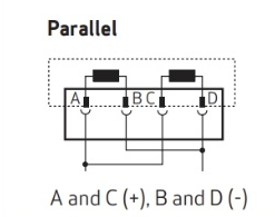
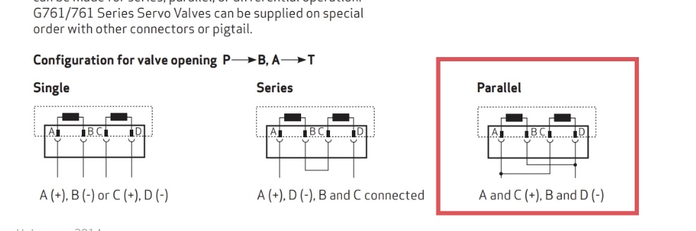
My understanding is that if I use the parallel connection method for the G761 (with A and C as signal positive, B and D as signal negative), each valve requires 40 mA, so four valves would need a total current of 160 mA. One VC2124 channel provides a maximum of 100 mA, so two channels need to be connected in parallel, each set to 80 mA.
If I use the series connection method for the G761 (A as signal positive, D as signal negative, B and C connected), the resistance of one G761 is 160 Ω. The total resistance of four G761 valves in series is 640 Ω, which exceeds the maximum load of 505 Ω for the VC2124’s 20 mA output.
If I choose the single connection method for the G761 (A as signal positive, B as signal negative), a G761 in single connection requires ±40 mA and has a resistance of 80 Ω. Four G761 valves connected in series give a total resistance of 320 Ω. In this configuration, the resistance per G761 is 80 Ω, and four in series make 320 Ω, which also exceeds the maximum resistance of 240 Ω supported by a single channel of the VC2124 when outputting 40 mA.
Conclusion: To control four G761 servo valves in parallel, at least two channels of the VC2124 must be used.
I agree with the conclusion, assuming a typical 40 mA valve. I believe the single coil configuration doesn’t really apply because I think it requires two outputs from the controller, and the RMC only has one output per axis.