An RMC75E will be used for dual control (position / single input force). For simulation purposes, a curve has been created to generate a force as a function of position. A ‘Move Absolute (20)’ causes a variable tied to the curve to change as the position changes. By setting the Secondary Feedback, ‘Using:’ selection to custom, the ‘Custom Counts (C)’ variable is available and is set in a continuously running program to the force value. What would be the next step to get the Actual Force to reflect this? We would like to simulate a sequence where we move to a position, change to force control and drive up to some limit, stop, and return.
The expression that assigns a value to the custom counts should be sufficient. That expression will use the _CrvInterpY function to get the force from the curve, given the current x value of the curve. I assume the currect x value is the Actual Position, but I am not entirely sure from your explanation. Once that calculated value is assigned to the Custom Counts tag, it should appear in the Actual Force. Keep in mind that the Force Scale and Offset will affect the value. If the Force Scale is 1 and the Force Offset is 0, then the Actual Force will be the same value as the Custom Counts were assigned by the expression.
-Jacob
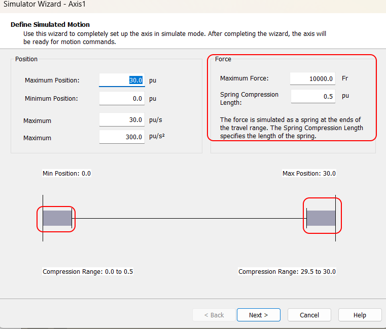
Did you notice that when you use the simulation wizard on a pressure/force axis it will setup simulated springs at both ends of the cylinder travel? If your position force profile is linear (or close to it) this would be an easier approach for testing purposes.
By default it will give you springs at both ends with 10,000 force units of resistance over 0.5 position units. This force increases linearly as the position moves into and through this range. You can customize these values in the Simulation Wizard.
The way you describe sounds way more fun but I have used this method to simulate position / force axes many times with success.