These steps come before actually tuning the gains.
Test Wiring and Polarity
Check the Deadband
Non-linear Valves
Adjust the Output Bias
Set Up the Tuning Tools
Set Symmetrical/Ratioed
I want to know what to pay attention to in addition to these.
1: the frequency curve of the speed and the voltage.
Is the speed curve a hysteresis voltage curve, a good hydraulic system, is there a requirement for this?
2: the consideration of linearity
E.g
Linear valve
0~8V voltage and speed have a better linearity. When more than 8V, the linearity is not good, although there is an increase, but the increase is not much.
1V—100mm/s 2v— 200mm/s 8V – 800mm/s 10V–820mm/s
How should we consider the voltage range of 8-10V?
The first thing I like to do after getting the actuator to move is to make open loop moves.
I want to check the polarity. Normally a positive voltage makes the actuator extend.
If not I need to check the invert output polarity box in the output section in the axis tools.
The next thing I do is output a small amount control signal. This checks for dead band but also if the system suffers from stick-slip.
I can also check if there are rough spots in the cylinder.
I use open loop rate to output more. I check for linearity and make sure the velocity is constant for a constant control output.
If not, why not? Sometimes the accumulator is not charged right so the pressure drops while moving and slows down.
Sometimes there are misaligned cylinders that will start to bind at one end of the stroke.
Another thing I look for is the response of the valve. When I start to ramp up the control signal in open loop I like to see the valve open up so the actuator starts moving within a millisecond or two.
The auto tuning assumes the valve does not have a dead band. Servo valves and servo solenoid valves should not have dead bands.
The flow should be reasonably linear with the control signal. It doesn’t need to be perfect but the more linear the better.
If the valve does not have a Bode plot it should not be used for servo control
Check the Bode plot. Valve manufacturers always use -3db or 90 phase lag to rate their valves.
This is optimistic. You should use the minimum frequency of where the valve gain drops below 0 and where the phase delay is 45 degrees. Do not use the 5% or 25% response. Use the 90% or 100% response.
Thanks
1:If there is a stick-slip phenomenon in the project,Can electrical parameters be compensated? Or the oil cylinder must be replaced?
stick-slip to bring what difficulties which the electrical commissioning
2: auto tuning
How to correctly select parameters Output voltage and ramp rate
If the parameters are too high, Too much of a shock, so I don’t use the maximum voltage and the slope now, In this case,Is it possible to get very accurate parameters?
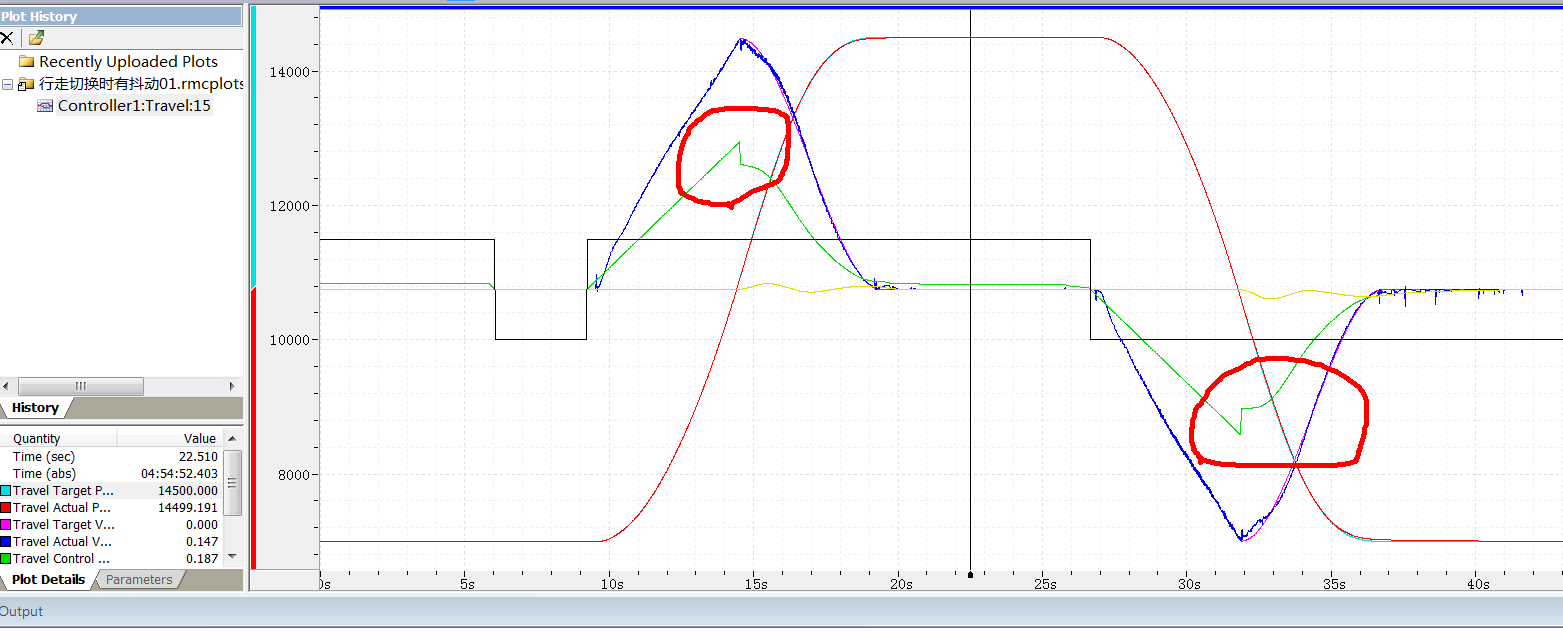
In my project,I used quick move Absolute function causing the system to jerk
I think Velocity Feed Forward is not correct,How can I get the correct Velocity Feed Forward
See attachment
3:In many hydraulic systems, the dead zone voltage of servo valves is asymmetrical, while in the rmctools parameters, it is considered symmetrical. How should we deal with this situation?
My right to deal with it now is
IF _Axis[0].ControlOutput>0.0 THEN
_Axis[0].OutputDeadband:=0.2 ;
ELSE
_Axis[0].OutputDeadband:=0.1 ;
END_IF
4:
The relationship between system pressure and driving pressure
The pressure used in the project is 21Mpa, and the driving pressure is 1.5MPa
If such a parameter is reasonable, the difference between the two is a little big.
The greater the driving pressure, the better the debug is right
Nice plot
I see no evidence of stick-slip. I do not see places where the position seems to stick.
It looks like quick moves.
The discontinuity in the control output is expected because the acceleration changed from positive to negative.
The problem is that the acceleration can not change instantly but the actual position seems to track the target position well.
Acceleration can not change instantly because that requires a instantaneous change in pressure.
Pressure cannot change instantly because that requires flow and changing flow requires moving the valve spool.
That is why s-curves should be use
Think about it. If this was a normal move absolute the acceleration feed forward would add extra output when accelerating and subtract output when decelerating. That is exactly what you see.
The tuning looks pretty good.
This is why we provide parameters. If you are auto tuning a heavy load the shock is undesirable.
Adjust the open loop rates until the acceleration is acceptable.
Higher acceleration and deceleration rates are necessary for auto tuning systems that have high natural frequency.
Lower accelerations are OK for systems with lower natural frequency.
The tuning looks pretty good.
It is best to zip the plot file. Then I can the response and parameters.
I cannot see what the yellow line is.
It looks like it may be the integrator.
If the integrator is close to zero the feed forwards are tuned up well
The problem is the rapid change from accelerating to decelerating.
That looks good.
What valve are you using where the dead band is not symmetrical?
Servo valves should not have a dead band.
4:
The relationship between system pressure and driving pressure
The pressure used in the project is 21Mpa, and the driving pressure is 1.5MPa
If such a parameter is reasonable, the difference between the two is a little big.
The greater the driving pressure, the better the debug is right
[/quote]