Using an RMC75 with very simple timed motions. The motions are very smooth, no overshoot. There is a steady state oscillation that seems to happen no seeming reason of very low frequency from 0.5 Hz to 6 Hz.
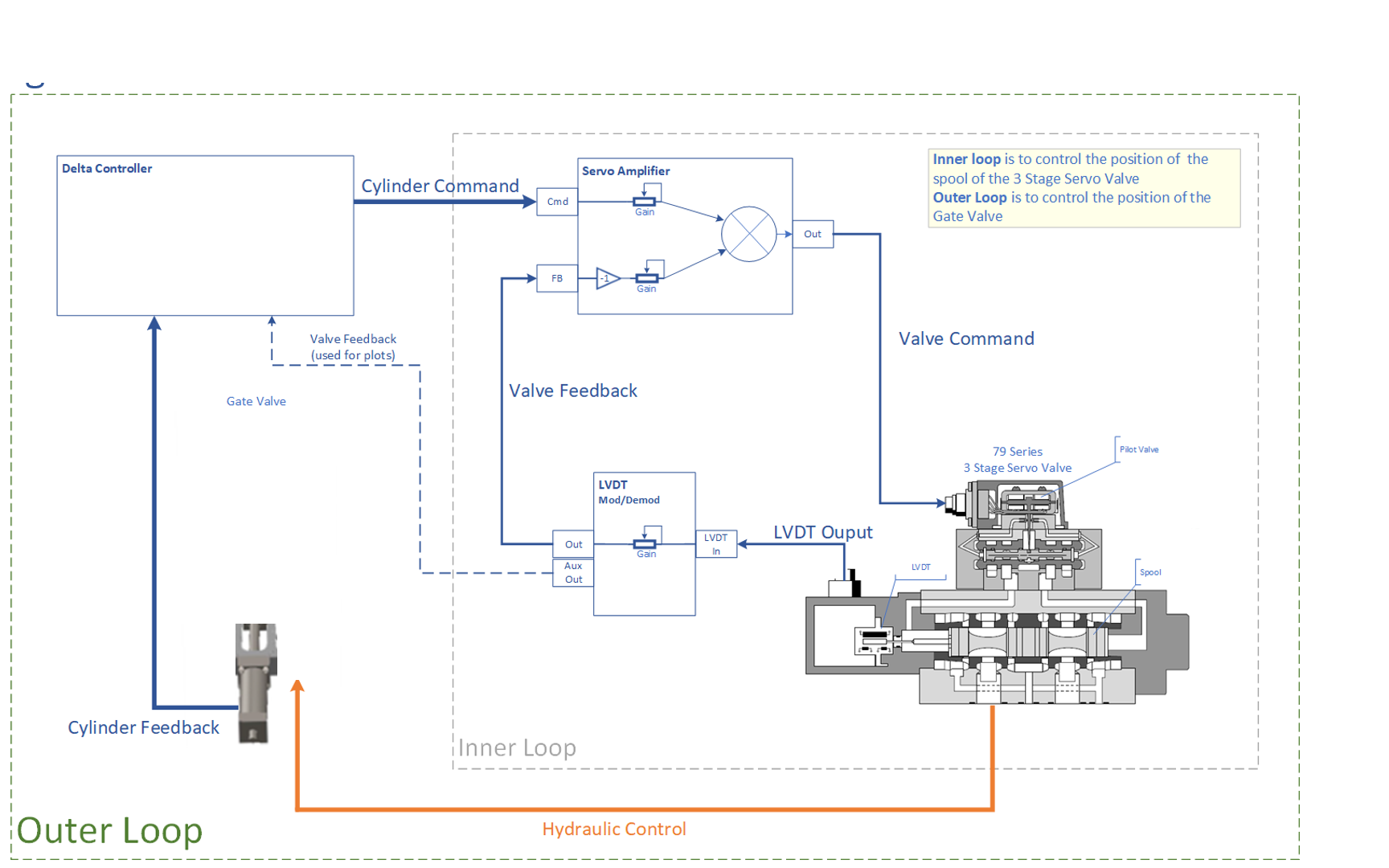
This system is the delta controller controls the outer loop and an inner loop takes Delta control voltage and the servo valve feedback LVDT signal to control the inner loop.
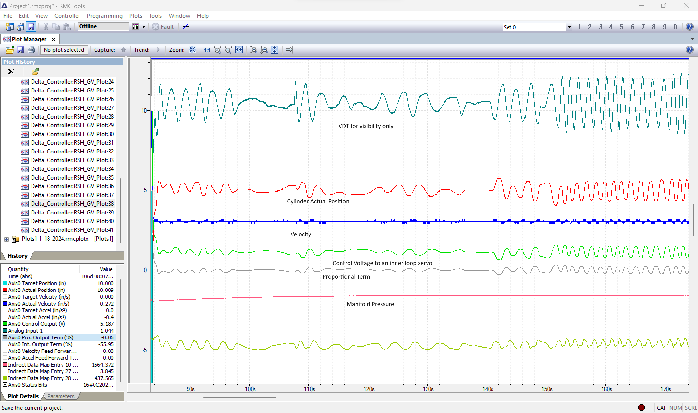
Attached is pic of fairly bad instance of the oscillations.
Could you attach a plot file, rather than the image? That will give more information, such as all the PID gains, and allow more comparison of plot lines to tell if the issue is with the inner loop or with the outer loop. Also, do you have more details on the valve, such as model number? I would like to check what the hysteresis of the valve is.
-Jacob
edit: I meant to add:
Indirect Data Map Entry 10 Value: system hydraulic pressure
Indirect Data Map Entry 27 Value: one side to cylinder pressure
Indirect Data Map Entry 28 Value: other side of cylinder pressure
Analog Input 1: LVDT mod/demod aux out voltage to the Delta for visibility
Which axis is the inner axis, and which is the outer? The plot only shows Axis 0.
From the gains included in the plot, I suspect that either one or the other axis isn’t quite tuned up yet. Have you tuned up the inner loop? The plot shows that the control is relying heavily on the integral gain, which makes the response very slow, and could contribute to the oscillation.
It could be that we need a different way to gear the inner loop to the outer loop. How are you doing that gearing now?
Jacob,
Right now the inner loop is an independent loop. I’ll include a block diagram… I’m thinking the best move might be to redesign this to use the cascade model i have seen on the rmctool manual. The integral term is only used on a decel. These oscillations have been present even when the Igain = 1.0.
I see, so from the RMC’s end it’s just a simple position axis control. That should be just fine. On the plot you sent, the first 40-50 seconds don’t really count, since it appears the axis was pushing up against the end, and when coming out of that, the integral gain was wound way up. However, later in the plot, the integral term is around -55% when the axis is stopped. This indicates the valve is way out of null. It would be nice if that could be adjusted - typically it’s a mechanical adjustment on the valve. When adjusted correctly, the integral term should be hovering around zero when the axis is stopped.
The move at about 80.5 seconds is commanding the axis to move faster than is possible, so the Control Output saturates. It would be nice if you could command some slower moves so that the Control Output does not saturate, then tune it according to the manual tuning procedure in the RMCTools help, or use the Tuning Wizard with the plot of motion (make sure to have just a basic move that doesn’t saturate).
For the oscillation, it seems that it takes some time for the valve to respond. If the tuning methods I recommended don’t help with the oscillation when holding position, we may need to add some Output Deadband, which helps prevent the integral gain from making the axis hunt around position. However, I think some tuning work has potential to help first.
Jacob,
Thank you for the advice… This particular valve doesn’t have a null, it does allow for adjustment of the transducer location. We will have to put that on the list of things to fix.
I did find some other moves at lower pressure, one direction is maxed out, which is the reason we upped the pressure. The other direction is not maxed and achieves good results. You’ll notice the jump at the beginning of the motion, which we fixed by taking out the integral zero operation before move, so you can ignore that. There still seems to be some LVDT “Analog Input 1” as the valve is hunting to it’s final location. They still are quite low in frequency, starting at about 5 Hz then to 2.6, then down to 1 or less. Any explanation, or fix for that? Thanks again.
Chip Plots 1-16-2024_Plot 6_trimmed.rmcplotx (848.2 KB)
Sorry, I see I had written about adding Output Deadband. I had meant Deadband Tolerance. I think the Output Deadband should be zero, and you can try a Deadband Tolerance value of about 0.05 for starters.
I also think you can improve the velocity feed forward on moves that don’t saturate. If you make sure to not clear the integrator before the move, then it will be easier to see what the velocity feed forward is doing.
Usually, the internal valve control is quite good so there isn’t any value to the cascaded loop being done in the RMC. I can’t say for sure on this valve, but Moog makes good product, so I wouldn’t be inclined to consider us doing the inner loop.
Jacob,
Help me understand this system. Looking at the attached file, I see the Int% trending down when Act > Tar, but when Act < Tar the Int% flat lines until 100.2 sec the Int% trends positive, in the attached file. Why didn’t it trend pos. at 62.96 when Act < Tar?
The question is why isn’t Int% ever going back to zero?
Is it our programming?
edit:
We already had a Deadband Tolerance: 0.05
Set Integrator Mode(71): Decel(4)
Default Integrator mode: TGDone
The system certain does behave rather unusually. The main issue to figure out is why the system requires valve requires around -5 V to hold position. This problem is not caused by your programming. I suspect that either there is a major problem with the valve, or there is a lot of leakage in the cylinder or somewhere between the valve and the cylinder. Do you have a schematic of the hydraulic system?
Is this a new installation or an old system that has started to behave badly?
Does the valve have an external pilot line to it? Is the pilot pressure correct? Is there a pilot filter that is plugged?
Does the valve have an external drain line to it? Is the drain plugged?
Does the valve have an internal filter screen. Many of the old servo valves did. When the screen gets plugged, the behavior of the valve gets strange.
Does the system have adequate filtration? Servo valves require very good filtration to keep them operating properly. Moog 79-series Catalog says cleanliness of 14/11 or better (ISO 4406 standard). It says, “The cleanliness of the hydraulic fluid greatly effects the performance (spool positioning, high resolution) and wear (metering edges, pressure gain, leakage) of the valve.”
Was any work done elsewhere in the system? Standard procedure is to remove servo valves during work or startup. Then flush the system clean before returning the servo valve to the system. If work was done with the valve in place there could be a contamination issue.
Is there an accumulator on the system that is not pre-charged properly or accidently valved out. When output saturates either the motion is faster than the system was designed for or something is preventing full flow from reaching the valve. Accumulator issues are one of these things.
Hope you get things figured out on your next visit to the site!
Norm
This is not a new installation, however this problem has been plaguing the system for awhile. I was brought in to try and fix it. I found one coil of the pilot valve not wired and thought that would solve all the problems, it helped with smoother moves but not total solution of the steady state oscillations.
To answer most of your other questions, the system designer has always been on site to help with preping the system so as far as i can tell everything is right, however I’m beginning to think oil is going somewhere it shouldn’t, i.e. internal leak, etc.
This system sat for a long time and it got contaminated. The system was flushed and cleaned, filters installed, kidney loop used regularly, valve served by Moog.
The accumulators have gauges where we can see what they are reading at all times.
Yes, to what you are saying about commanding more speed than the valve can provide. That is why we keep upping the pressure, to achieve the speed. The increased pressure exacerbates the oscillations problems.
The other issue is we have to hold very tight tolerances at the closed and open positions. I don’t exactly know what these are but I would think +/- 0.002.
If the problem has been getting progressively worse, the most likely suspect is contamination. Have you sent an oil sample for testing? As mentioned, the servo valve itself is very sensitive to contamination. But seeing the check valves in the circuit, contamination could also be holding one of them slightly open when it should be closed. That’s no good either.
In the circuit, the flow control valve labeled “SET AT 30 GPM” seems suspect to me. The circuit seems to depend on this being closed enough to let the pressure to extend the cylinder keep YCV6703 closed. I would do a test where I close this valve completely and see how the system performs. Note how many turns it took to close so you can put it back after the test.
I was looking at some data from before i was involved and it looks like the oscillations are identical as now in terms of frequency and amplitude. The system was cleaned, flushed, valves sent off Jan 2023. The data I’m seeing is from Apr 2023, and got involved Jun 2023. Found the unwired coil on the pilot in Jun 2023. I think moves were smoother but steady state oscillations are unchanged for 2023.
Maybe it’s time to ask about the check valves, on my end… I really thought this was gonna be a straight valve tuning job.
That set at 30 GPM is part of the emergency close circuit, i believe.
That set at 30 GPM is part of the emergency close circuit, i believe
Yes. I wasn’t suggesting to leave it closed, just close it for a test. If the cylinder behaves well with it closed then the valve could have been set too far open or one of the downstream check valves might be malfunctioning.
Then it would be set back properly after the test. Troubleshooting is always running a lot of “what-if” scenarios and trying to separate parts of the circuit to see if they may be malfunctioning.