One method of designing a system that requires high flow and high precision is to use two valves, where one is low flow, and the other is high flow. Transitioning between the valves can be a challenge. One way to do so very smoothly is described here. An RMCTools project demonstrating this is also attached at the end.
Approach
The main axis to which the position feedback is connected is configured as an outer loop axis. The outer loop axis commands two output only axes, one for each valve. The valves will open and closed based off user-generated curves and the current Control Output of the outer loop axis.
Theory
The curves are designed such that the small valve range will be -100% to 100% when the Outer Loop axis’ Control Output goes from -x% to x%, where x = Small Flow / (Large Flow + Small Flow) x 100%. Then, the large valve will kick in.
These curves should result in the linear total flow, so that the feed forwards and gains of the main outer loop axis can operate as normal.
Designing the curves
The curves are very simple, as shown below. The Control Output Transition point, Ct, is:
Ct = Small Flow / (Large Flow + Small Flow )
Small valve curve:
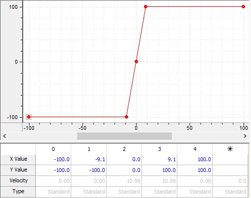
Large valve curve:
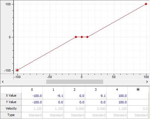
Added together, the resulting flow will be linear.
User Program
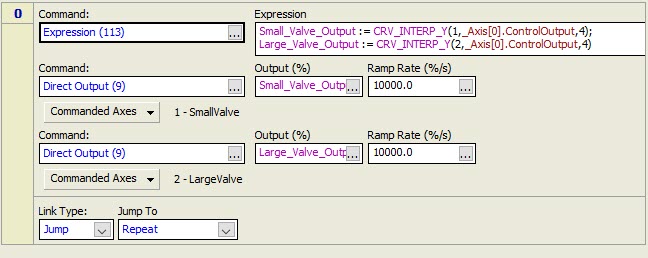
The following continuously-running user program will apply the curves to each valve:
Requirements and Limitations:
- Requires user program to always run
The user program must always be running. See https://forum.deltamotion.com/t/make-a-user-program-always-run/436 - Use high-performance, linear valves
To be successful, the valves must be high-response, zero-lapped, with a linear flow. - Cannot auto-tune
The axis cannot be auto-tuned, since autotuning requires that the controller be in program mode. Instead, start tuning manually with the P gain, generate a couple good plots of motion in each direction, then use the tuning wizard with existing plot.
Valve Voltage Transition.rmcproj (33.2 KB)